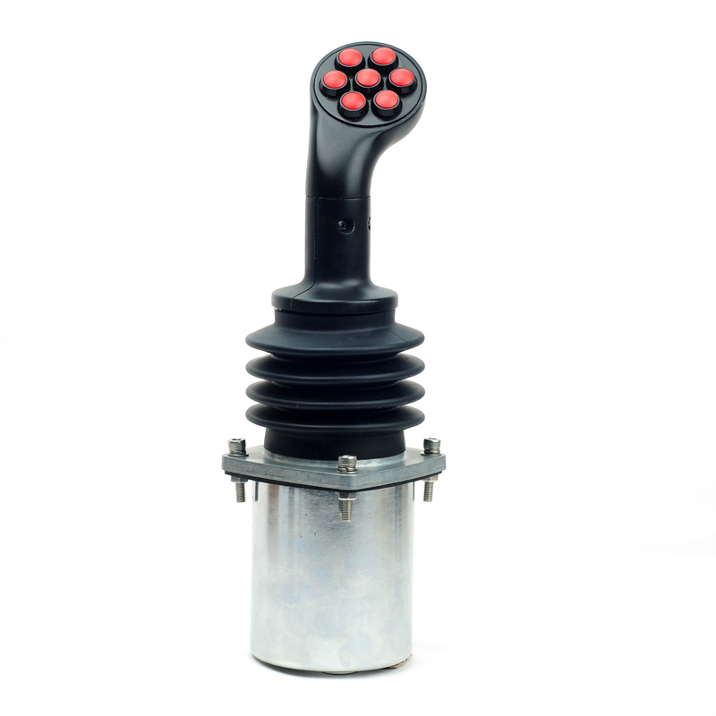
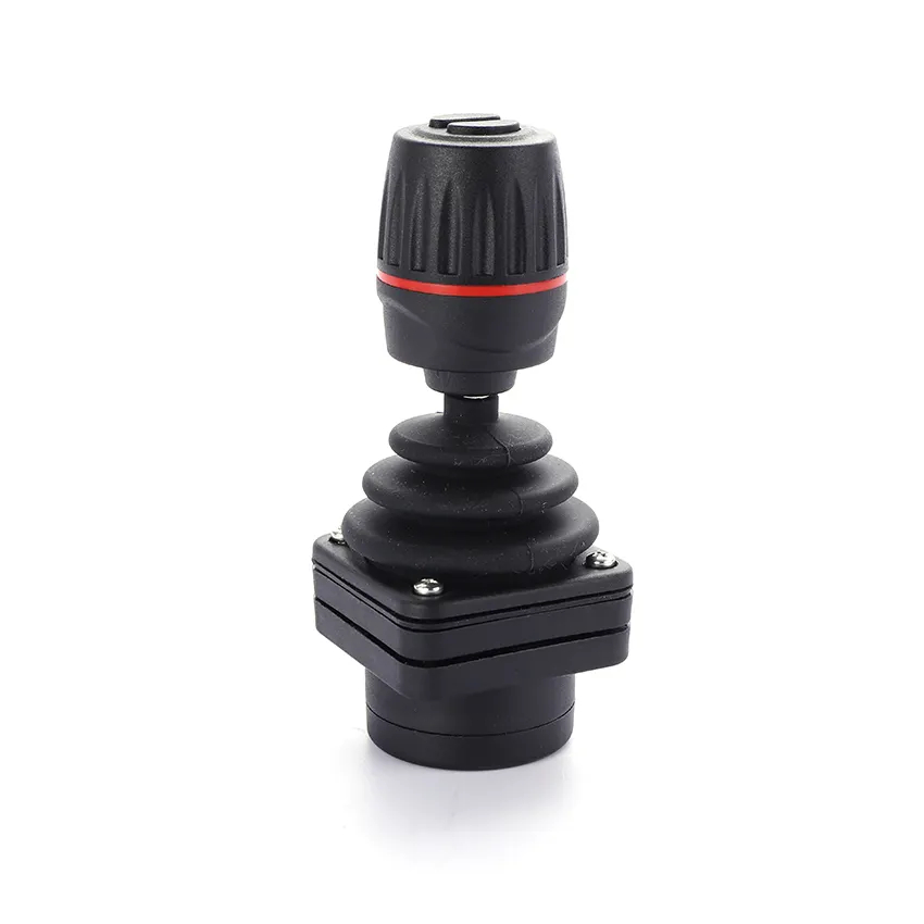
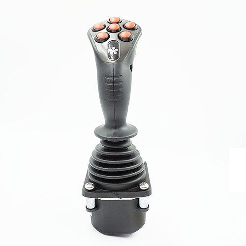
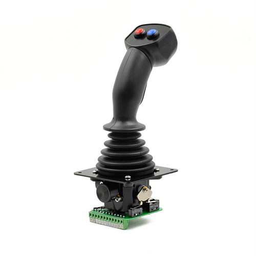
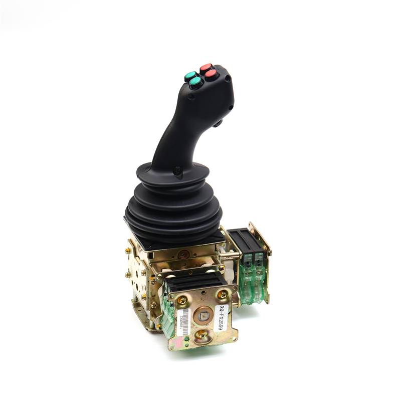
Recommended Products
Contact Us


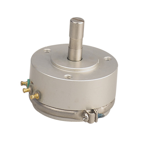
Product Features
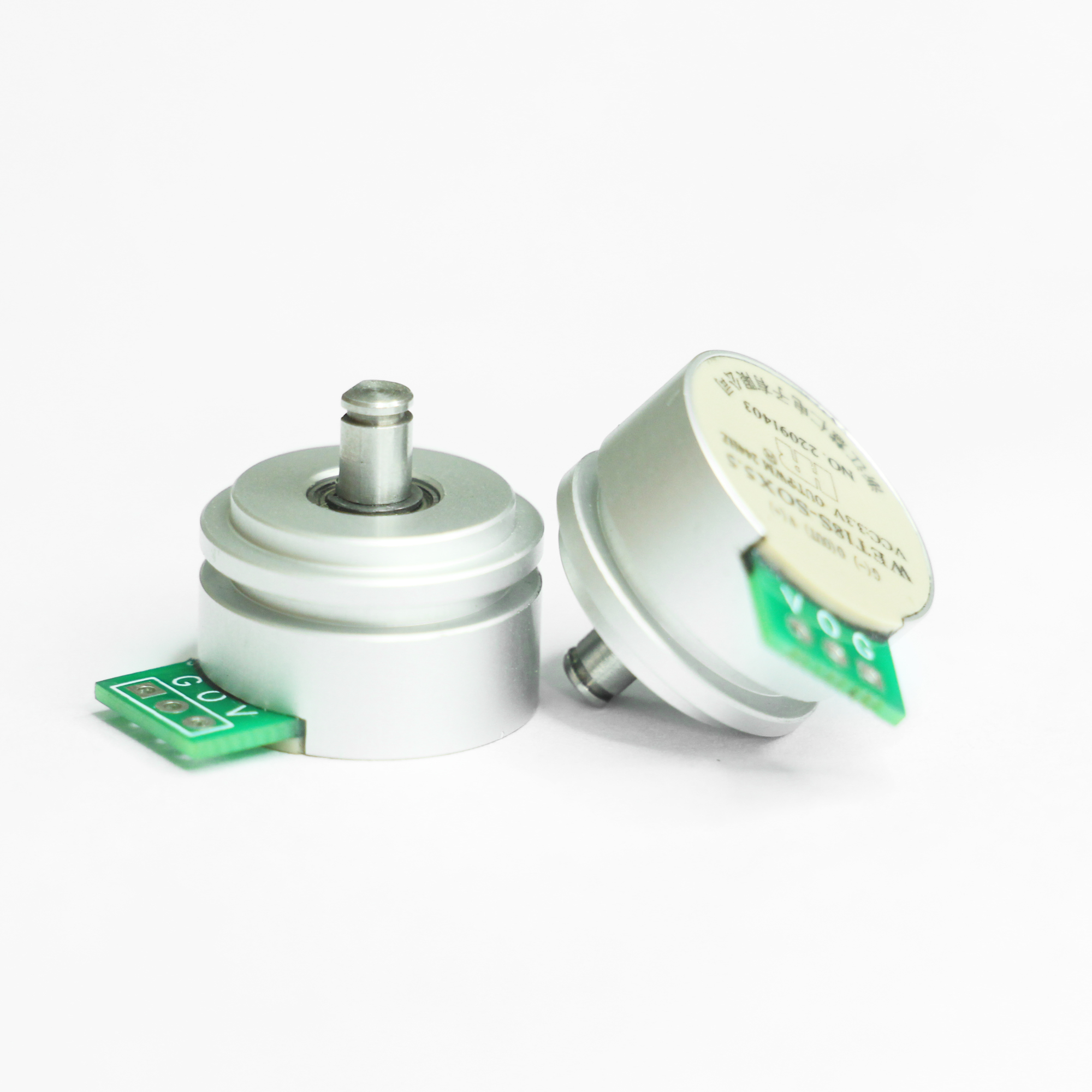
● Non-contact digital potentiometer
● High precision, long life
● Any electrical Angle choice, customized for you
● Cable discharge mode: Side cable discharge
| Outgoing terminal name | Exit connection |
| V(+) | Power +: 5VDC |
| G(-) | Power -: 0VDC |
| O(OUT) | Output pin: PWM 250Hz |

Mechanical Travel | 360° (endless ) | Life Expectancy | Theoretical infinite |
Operating Temperature | -40℃~+125℃ | Rotational speed | <30000RPM |
RS | |||
Storage temperature | -40℃~+125℃ | Shell | Aluminum |
Running torque | <5mN·m | Shaft | Stainless iron |
Electrical Travel | 356° |
Independent Linearity | ±0.3% |
Resolution | 4096(12 bits) |
Operating voltage | 5VDC |
Output signal | PWM 250Hz |
Max operating current | <10mA |
Initial terminal output deviation | <10mV |
Load resistance | >5KΩ |
Electrical part | Output range | Standard output 0~100% (customizable) |
Output direction | The standard is clockwise signal output, but it can also be set to counterclockwise signal output | |
Other output modes | Current such as :4~20mA output, PWM output... | |
Special shaft | Special shaft length, special shaft diameter, or special machining on the shaft can be done according to customer requirements |
18 e type l digital r potentiometer t test method
1. Required tools, instruments and equipment A small flat-blade screwdriver, a thermal melt gun, a Tektronix oscilloscope, a DC regulated power supply, and an electric rotary digital display indexing table.
2. Measurement
1. First fix the potentiometer to be measured on the electric rotary indexing table, and fix it with hot melt glue to prevent errors caused
by tooling gaps when adjusting the angle;
2. Connect the power lines V and G of the potentiometer to the DC regulated power supply, connect the output signal lines O and G to the first probe of the oscilloscope channel, and turn on the power switch of the oscilloscope to preheat in advance;
3. Turn the output adjustment knob of the DC stabilized power supply to the minimum, then turn on the power supply, and adjust the output voltage to 5VDC;
4. Observe the oscilloscope and record the PWM frequency;
5. Rotate the indexing table to make the potentiometer rotate clockwise, and observe whether the signal duty ratio gradually increases;
6. Rotate the indexing table to find the position with a duty cycle of 5%, and the angle display of the indexing table returns to zero;
7. One test point at 10°, record the angle and duty cycle data;
8. Calculate the angle deviation after the test is completed. If the angle deviation is less than 0.7°, the potentiometer is judged to be
qualified.
HuiRen Electronic is proud to be one of the leader of condustive plastic potentiometer , Industrial joystick.
Copyright©2023 Zhejiang huiren electronics co., ltd
Design By: 057123.com
 浙公网安备 33059102000323号