Контакты
Single-axis hand operated joystick
Product Features
● Single-axis forward and backward directional or single directional operated
● Friction lock or spring return, Center and start (end) position mechanical lock optional
● Hall effect or potentiometer angle detection optional
● Microswitch optional (maximum 10A@30Vdc)
● Various handle optional
Application
Typical application on various electro-hydraulic control system of engineering vehicles and other electrical control system
| Travel angle | ±37.5º or 75°(single direction) |
| Operating type | Spring return or firction |
| Breakout force | 8N (spring) 16N (friction) |
| Operating force(max) | 18N (spring) 16N (friction) |
| Maximum allowable force | >300N |
| Expecting life | >2 million cycles(potentiometer) |
| >5million cycles (hall effect) | |
| Weight | 500g (without handle) |
| Potentiometer | |
| Power supply | <36Vdc |
| resistance | 10KΩ (±10%) |
| Center angle | ±3º |
| Maximum dissipation | 0.2W |
| Hall effect | |
| Power supply | 5.0±0.5Vdc |
| Supply current (nominal power supply) | <11mA |
| Maximum allowable overload voltage | 20Vdc |
| Reverse maximum allowance voltage | -10Vdc |
| Output linearity tolerance | <±0.2V |
| With electronic amplifier | |
| Power supply | 9~18Vdc (U11~U15) |
| 18~36Vdc (U21~U25) | |
| 9~36Vdc (I21-I22) | |
| Power current consumption | <20mA |
| Maximum output current | 10mA (Standard power supply) |
| Microswitch | |
| Load capacity | 10A@30Vdc (Resistive load) |
| Expecting life | 30 million times (Mechanical) |
| 100 thousand times (Electrical) | |
| Insulation resistance | >100MΩ (500Vdc Insulating-resistance meter) |
| Breakout angle | ±5° |
| Operating Temperature | -30℃~+70℃ |
| Storage Temperature | -40℃~+85℃ |
| Protection level | IP65 (Above the flange) |
| type | SJ20 - □□ - □□ - □□ - □□ - □□ - □□ |
| Code | ① - ② - ③ - ④ - ⑤ - ⑥ - ⑦ |
1. Product type
SJ20 series joystick, single-axis friction lock or spring return, installation dimension58mm
2. Operating type
| FCF | Friction, center detent |
| FEF | Friction, start (or end )detent |
| FCL | Friction, center mechanical lock |
| FEL | Friction, start (or end) mechanical lock |
| SC0 | Spring return, back center position |
| SCL | Spring return, back center ,center with mechanical lock |
| SE0 | Spring return, back start position |
| SEL | Spring return, back start position ,start(or end) with mechanical lock |
Notice:Mechanical lock is only used in BG handles.
3. Output signal
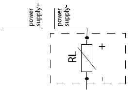
| P101 | Potentiometer, less than 36Vdc power supply, with 10KΩ center-tapped potentiometer |
| H51 | Hall effect,5Vdcpower supply, 0.5~2.5~4.5V output voltage |
| H52 | Hall effect,5Vdcpower supply, 0~2.5~5.0V output voltage |
| H53 | Hall effect,5Vdc power supply, 1.25~2.5~3.75V output voltage |
| U11 | With electronic amplifier,9~18Vdc power supply, -10V~0V~+10V output voltage |
| U12 | With electronic amplifier,9~18Vdc power supply, +10V~0V~+10V output voltage |
| U13 | With electronic amplifier,9~18Vdc power supply, -5V~0V~+5V output voltage |
| U14 | With electronic amplifier,9~18Vdc power supply, +5V~0V~+5V output voltage |
| U15 | With electronic amplifier,9~18Vdc power supply, 0~+10V output voltage |
| U21 | With electronic amplifier,18~36Vdcpower supply, -10V~0V~+10V output voltage |
| U22 | With electronic amplifier,18~36Vdc power supply, +10V~0V~+10V output voltage |
| U23 | With electronic amplifier,18~36Vdcpower supply, -5V~0V~+5V output voltage |
| U24 | With electronic amplifier, 18-36Vdc power supply, +5V~0V~+5V output voltage |
| U25 | With electronic amplifier,18-36Vdc power supply, 0~+10V output voltage |
| U26 | With electronic amplifier,18-36Vdc power supply, 6V~12V~+18V output voltage |
| I21 | With electronic amplifier,9-36Vdc power supply, 2-wire system 4mA~12mA~20mA output current |
| I22 | With electronic amplifier,9-36Vdc power supply, 2-wire system 20mA~4mA~20mA output current |
| NA | Without analog output |
4. Microswitch
| MS00 | Without microswitch |
| MS21 | With 10A start position microswitch |
| MS22 | With 10A forward and backward directional microswitch |
| MS23 | With 10A center(N.C.) and forward and backward directional microswitch |
5. Handle
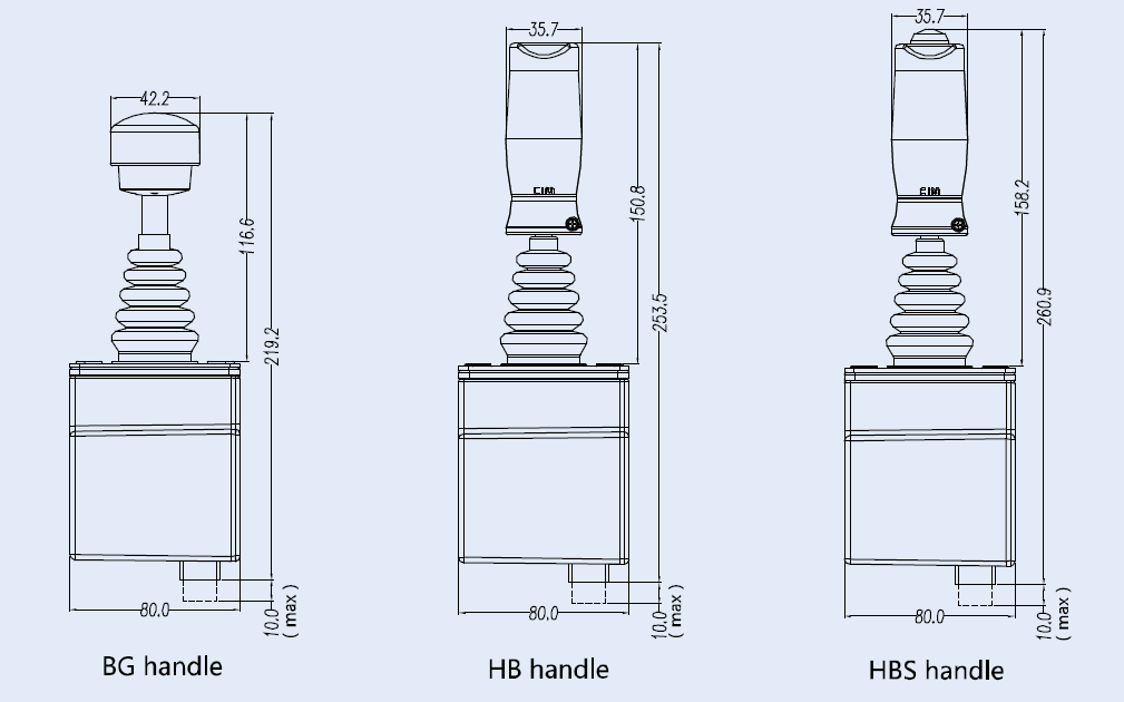
| BG | BG type handle,handle operate |
| HB | HB type handle,top without button |
| HBS | HBS type handle,top with button |
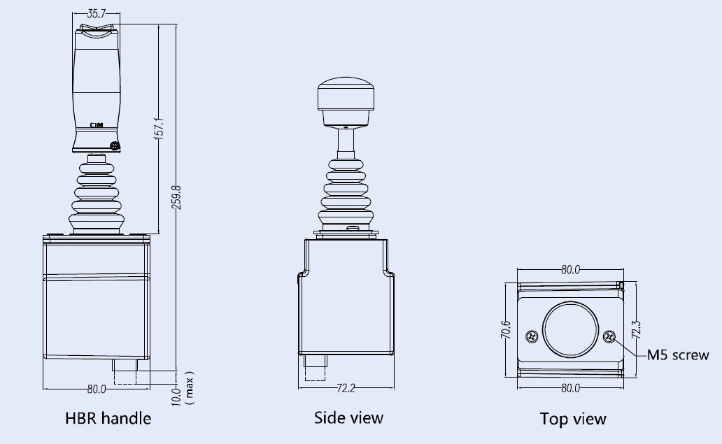
| HBR | HBR type handle,top with rocker switch |
6. Connection
| L | Wire output (without housing) |
| A | AMP connector |


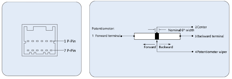
| Pin | Potentiometer | Hall effect |
| 1 | Potentiometer forward terminal | +5V |
| 2 | Potentiometer center tap | N/A |
| Single direction(N/A) | ||
| 3 | Potentiometer backward terminal | 0V |
| 4 | Potentiometer wiper | Output |
| 5 | Directional switch forward (N.O.) | Directional switch forward (N.O.) |
| Start position switch of single direction (N.O.) | Start position switch of single direction (N.O.) | |
| 6 | Forward directional switch common terminal | Forward directional switch common terminal |
| Common terminal of start position | Common terminal of start position | |
| 7 | Directional switch back ward (N.O.) | Directional switch back ward (N.O.) |
| Single direction (N/A) | Single direction (N/A) | |
| 8 | Backward directional common terminal | Backward directional common terminal |
| Single direction (N/A) | Single direction (N/A) | |
| 9 | Rocker left directional (N.O.) | Rocker left directional (N.O.) |
| 10 | Handle of top switch common terminal | Handle of top switch common terminal |
| 11 | Rocker right directional (N.O.) | Rocker right directional (N.O.) |
| 12 | Deadman switch | Deadman switch |
| pin | With electrical amplifier of output voltage | With electrical amplifier of output current |
| 1 | Power supply |  |
| 2 | GND | |
| 3 | Output positive(+) | N/A |
| 4 | Output negative(-) | N/A |
| 5 | Directional switch forward (N.O.) | Directional switch forward (N.O.) |
| Start position switch of single direction (N.O.) | Start position switch of single direction (N.O.) | |
| 6 | Forward directional switch common terminal | Forward directional switch common terminal |
| Common terminal of start position | Common terminal of start position | |
| 7 | Directional switch backward (N.O.) | Directional switch backward (N.O.) |
| Single direction (N/A) | Single direction (N/A) | |
| 8 | Backward directional common terminal | Backward directional common terminal |
| Single direction (N/A) | Single direction (N/A) | |
| 9 | Rocker left directional (N.O.) | Rocker left directional (N.O.) |
| 10 | Handle of top switch common terminal | Handle of top switch common terminal |
| 11 | Rocker right directional (N.O.) | Rocker right directional (N.O.) |
| 12 | Deadman switch | Deadman switch |